Wednesday, June 2, 2010

RGB 4x4x4 LED Cube.


Welcome!

I would like to present one of my finished project. I don't have much time so the presentation will be short and not detailed. I hope you will forgive me it. Inspiration to build such thing was similar devices presented on the Internet network. I am programmer at work and electronic hobbyist at private life so every kind of project that use microcontrolers I like a lot.


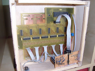
I know that this construction isn't perfect. Parts used to build I get from my home inventory. Don't ask why I use such parts. I just had have it. RGB LED's with common cathode was only bought. Patterns displayed by lamp are created by multiplexing each level of lamp. During one frame only one level is power on so 4*4*3 LED's are light at the time max. Each LED anode (individual colors) are connected in a column line driven by UDN2981A buffer controlled by 48 bit shift register (6 * 74HCT595N). Each cathode from the same level are connected to the same line driven by ULN2803A. ATMega32 is a heart of this device. Whole lamp can be driven only by 7 digit lines so you can use any other AVR device.


You can easily extend 4x4x4 LED's cube if you want. Firmware was wrote using C and AVRStudio/AVRlib. Below you can find circuit, PCB board and firmware. Hope it will be helpful.

Monday, May 17, 2010

A logic analyzer using the PC's parallel port.

Based on this two articles (first, second) I decided to build LPT logic analyzer. I will use it to debug work of the i2c-tiny-usb device.

Here you can find modified PCB to use it with thermal manufacturing mode.


Here you can find assembled pcb. Now I need to test how it works.

Thursday, April 8, 2010

i2c-tiny-usb PCB board adapted to the thermal hobby manufacture method.

Ok! So lets start my blog.
My name is Adrian Kurek and I am big fan of the electronics and robotics.

This is my first post so Please Welcome!

Some time ago I decided to build i2c-tinu-usb adapter.
http://www.harbaum.org/till/i2c_tiny_usb/index.shtml
I would like to make PCB using thermal method. The board was to complicated for this. I modified the PCB layout and here are the results of my work.

How the thermal method works in general? You need to print PCB mirrored image using gloss paper and laser printer. Put hot iron upside down. Put PCB laminate on hot surface copper upside. Put print on copper surface toner downside. Use cloth to press the print and move toner layer to the PCB. Cool down the PCB. Don't remove print jet! Put everything to the worm water with detergent. Wait a couple of minutes. Slowly remove paper from PCB. That's it! PCB layout is ready.

Since you can create one layer PCB only using this method you need to create two PCB with one layer and then glue it.


This is final PCB.


Board is fully assembled now. I am now in process of triggering it. I build LPT logic analyzer to get more information about running device.